Przeszukaj forum
Pokazywanie wyników dla tagów 'FFT'.
Znaleziono 2 wyniki
-
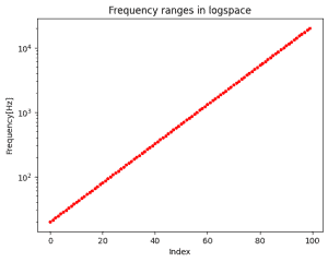
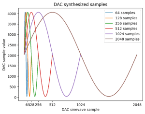
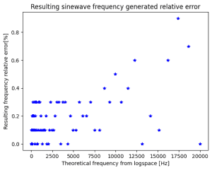
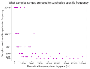
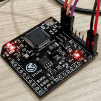
Kontynuacja tematu analizy widma audio. To już prawie 2 lata z przerwami 🙂 Niedawno nieco niepewnie wrzuciłem pierwszą wzmiankę o projekcie w wspólny worklog, ale temat się trzyma więc dorzucam osobny worklog. Jak ostatnio link na githuba z projektem PCB, programem, notatnikiem Jupyter z obliczeniami i pomiarami: https://github.com/Gieneq/FFTSlice W tej aktualizacji doszła całkiem dobra metoda generowania sinusoid z DAC. Po tym jak odpaliłem DAC, przypomniałem sobie dlaczego kiedyś odrzuciłem tę opcję. Wygenerowanie dowolnej częstotliwości nie jest takie oczywiste bo trzeba regulować częstotliwość timera i ewentualnie wybrać inną rozdzielczość spóbkowania sinusoidy. Dlatego uprościłem sytuację i pomyślałem że dla potrzeb analizatora widma audio potrzebuję tylko 100 częstotliwości pomiędzy 20Hz a 20kHz. Podzieliłem przedział logarytmicznie dla lepszej percepcji: Mikrokontroler STM32G081RBT nie ma za dużo pamięci, ale 6 spróbkowanych sinusoid zapisanych na uint16_t może być. Wartości narastają od 64 do 2048. Następnie trzeba przyporządkować próbki do częstotliwości jakie chcę wygenerować. Większe rozdzielczości lepiej nadają się dla niskich częstotliwości, a mniejsze rozdzielczości do szybszych przebiegów. Skrypt w Pythonie pomógł mi dokonać takiego przyporządkowania minimalizując czas w którym sygnał pozostaje na tym samym poziomie przy zachowaniu niezadużego odchylenia od oczekiwanej częstotliwości: Błąd poniżej 1% to całkiem dobry wynik. Przyporządkowanie jest dość proporcjonalne: W tabelce widać co by się działo gdyby skorzystać z tej samej rozdzielczości próbek - dla wysokich częstotliwości 1024 próbek ni jak nie pasuje: Pozostały testy, porównałem teoretycznie obliczoną częstotliwość z pomiarami picoscopem i wyniki są zgodne z oczekiwaniami. Tu wybrana wartość 1068Hz: Jestem trochę zaskoczony, że tak dobrze to działa 😅 w kolejnej aktualizacji chcę dodać opcję kolejkowania zmiany częstotliwości, żeby następowała po zakończeniu odtwarzania okresu sinusoidy - żeby nie było ucięcia w środku co wiązałoby się z trzaskiem od tak wygenerowanej wysokiej częstotliwości. Następnie pozostaje przetestowanie PGA i dodanie interfejsu SPI.
-
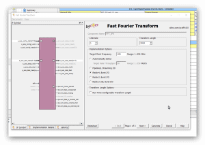
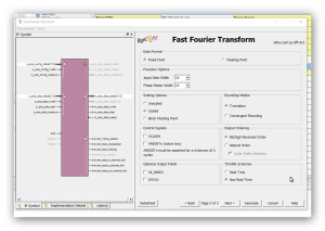
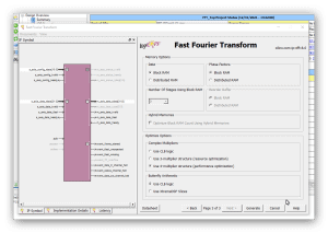
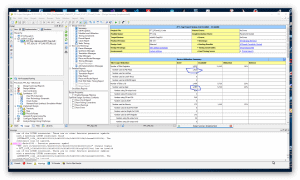
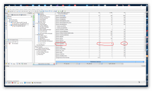
Cześć, jak wspomniałem wcześniej w wątku: Chciałbym porównać szybkość działania algorytmu FFT z użyciem "IP Core FFT" Xilinx'a. Mam zamiar wykonać próby na trzech zestawach FPGA (1024 próbki - 16 bit na próbkę - fixed point): 1) Elbert V.2 - Spartan3A (XC3S50A): brak bloków DSP i trzy sprzętowe układy mnożące 2) Mimas V.2 - Spartan6 (XC6SLX9) : 16 bloków DSP48 3) CMod A7-35 - Artix7 -(XC7A35T): 90 bloków DSP48 Z trzema różnymi częstotliwościami zegara układów FPGA. Rozpocząłem od projektu dla układu FPGA Spartan6(XC6SLX9 in CSG324 package) z zestawu MImas V.2: https://numato.com/product/mimas-v2-spartan-6-fpga-development-board-with-ddr-sdram/ Parametry IP Core FFT w wersji 8.0 Xilinx'a są tak dobrane tak, aby transformata FFT miała długość 1024 punkty i precyzję próbek 16-bit "fixed point" (z zegarem 100 MHz). Po ustawieniu parametrów IP Core jak jest przedstawione na kolejnych zrzutach ekranu: ekran 1 - długość transformaty 1024 punkty 1 kanał i opcja implementacji: "Radix-4, Burst I/O" (optymalizacja ze względu na czas wykonania(). ekran 2 - Precyzja 16-bit "scaled" ekran 3 - użycie "Block RAM", "Use 4-multipler structure" (optymalizacja z użyciem bloków DSP), "Arytmetyka Butterfly" z użyciem bloków CLB. Aby zorientować się jak działają konkretne wybrane opcje polecam przeczytać ten artykuł: https://www.allaboutcircuits.com/technical-articles/xilinx-fft-ip-core-fast-fourier-transform-software-walkthrough/ Po zakończeniu wyboru opcji dla "IP Core FFT V.8" i generacji jego modułów dodałem "top entity" (o nazwie: FFT_Top) w którym wywołuje(komponent) instancję IP Core FFT o nazwie " FFT_IP8". Na tym etapie jest to mi potrzebne wyłącznie w tym celu, aby móc uruchomić syntezę i implementację projektu w celu oszacowania liczby zasobów układu FPGA zużywanych przez projekt. I po zakończeniu fazy syntezy i implementacji można już podać liczbę podstawowych zużywanych zasobów: 1) Liczba przerzutników (FF) 1925 2) Liczba LUT 1468 3) Liczba użytych bloków DSP48 - 12 z 16 dostępnych (dla tej wersji układu Spartan6) Nie jest to mało - patrz zrzuty ekranu z ISE: Tutaj podaję kod głównego entity projektu (okazało się, że w przypadku tego IP Core jedyny wybór to język VHDL): ---------------------------------------------------------------------------------- -- Company: -- Engineer: -- -- Create Date: 13:32:16 12/31/2021 -- Design Name: -- Module Name: FFT_Top - Behavioral -- Project Name: -- Target Devices: -- Tool versions: -- Description: -- -- Dependencies: -- -- Revision: -- Revision 0.01 - File Created -- Additional Comments: -- ---------------------------------------------------------------------------------- library IEEE; use IEEE.STD_LOGIC_1164.ALL; -- Uncomment the following library declaration if using -- arithmetic functions with Signed or Unsigned values --use IEEE.NUMERIC_STD.ALL; -- Uncomment the following library declaration if instantiating -- any Xilinx primitives in this code. --library UNISIM; --use UNISIM.VComponents.all; entity FFT_Top is port ( aclk : in STD_LOGIC := 'X'; s_axis_config_tvalid : in STD_LOGIC := 'X'; s_axis_data_tvalid : in STD_LOGIC := 'X'; s_axis_data_tlast : in STD_LOGIC := 'X'; m_axis_data_tready : in STD_LOGIC := 'X'; s_axis_config_tready : out STD_LOGIC; s_axis_data_tready : out STD_LOGIC; m_axis_data_tvalid : out STD_LOGIC; m_axis_data_tlast : out STD_LOGIC; event_frame_started : out STD_LOGIC; event_tlast_unexpected : out STD_LOGIC; event_tlast_missing : out STD_LOGIC; event_status_channel_halt : out STD_LOGIC; event_data_in_channel_halt : out STD_LOGIC; event_data_out_channel_halt : out STD_LOGIC; s_axis_config_tdata : in STD_LOGIC_VECTOR ( 15 downto 0 ); s_axis_data_tdata : in STD_LOGIC_VECTOR ( 31 downto 0 ); m_axis_data_tdata : out STD_LOGIC_VECTOR ( 31 downto 0 ) ); end FFT_Top; architecture Behavioral of FFT_Top is ------------- Begin Cut here for COMPONENT Declaration ------ COMP_TAG COMPONENT FFT_IP8 PORT ( aclk : IN STD_LOGIC; s_axis_config_tdata : IN STD_LOGIC_VECTOR(15 DOWNTO 0); s_axis_config_tvalid : IN STD_LOGIC; s_axis_config_tready : OUT STD_LOGIC; s_axis_data_tdata : IN STD_LOGIC_VECTOR(31 DOWNTO 0); s_axis_data_tvalid : IN STD_LOGIC; s_axis_data_tready : OUT STD_LOGIC; s_axis_data_tlast : IN STD_LOGIC; m_axis_data_tdata : OUT STD_LOGIC_VECTOR(31 DOWNTO 0); m_axis_data_tvalid : OUT STD_LOGIC; m_axis_data_tready : IN STD_LOGIC; m_axis_data_tlast : OUT STD_LOGIC; event_frame_started : OUT STD_LOGIC; event_tlast_unexpected : OUT STD_LOGIC; event_tlast_missing : OUT STD_LOGIC; event_status_channel_halt : OUT STD_LOGIC; event_data_in_channel_halt : OUT STD_LOGIC; event_data_out_channel_halt : OUT STD_LOGIC ); END COMPONENT; -- COMP_TAG_END ------ End COMPONENT Declaration ------------ begin ------------- Begin Cut here for INSTANTIATION Template ----- INST_TAG FFT_1024_16 : FFT_IP8 PORT MAP ( aclk => aclk, s_axis_config_tdata => s_axis_config_tdata, s_axis_config_tvalid => s_axis_config_tvalid, s_axis_config_tready => s_axis_config_tready, s_axis_data_tdata => s_axis_data_tdata, s_axis_data_tvalid => s_axis_data_tvalid, s_axis_data_tready => s_axis_data_tready, s_axis_data_tlast => s_axis_data_tlast, m_axis_data_tdata => m_axis_data_tdata, m_axis_data_tvalid => m_axis_data_tvalid, m_axis_data_tready => m_axis_data_tready, m_axis_data_tlast => m_axis_data_tlast, event_frame_started => event_frame_started, event_tlast_unexpected => event_tlast_unexpected, event_tlast_missing => event_tlast_missing, event_status_channel_halt => event_status_channel_halt, event_data_in_channel_halt => event_data_in_channel_halt, event_data_out_channel_halt => event_data_out_channel_halt ); -- INST_TAG_END ------ End INSTANTIATION Template ------------ end Behavioral; Podczas generacji modułów "IP Core FFT V.8" został także utworzony test-bench, który zamierzam wykorzystać do pierwszych testów FFT - oto jego kod: --------------------------------------------------------------------------- -- -- (c) Copyright 2010 Xilinx, Inc. All rights reserved. -- -- This file contains confidential and proprietary information -- of Xilinx, Inc. and is protected under U.S. and -- international copyright and other intellectual property -- laws. -- -- DISCLAIMER -- This disclaimer is not a license and does not grant any -- rights to the materials distributed herewith. Except as -- otherwise provided in a valid license issued to you by -- Xilinx, and to the maximum extent permitted by applicable -- law: (1) THESE MATERIALS ARE MADE AVAILABLE "AS IS" AND -- WITH ALL FAULTS, AND XILINX HEREBY DISCLAIMS ALL WARRANTIES -- AND CONDITIONS, EXPRESS, IMPLIED, OR STATUTORY, INCLUDING -- BUT NOT LIMITED TO WARRANTIES OF MERCHANTABILITY, NON- -- INFRINGEMENT, OR FITNESS FOR ANY PARTICULAR PURPOSE; and -- (2) Xilinx shall not be liable (whether in contract or tort, -- including negligence, or under any other theory of -- liability) for any loss or damage of any kind or nature -- related to, arising under or in connection with these -- materials, including for any direct, or any indirect, -- special, incidental, or consequential loss or damage -- (including loss of data, profits, goodwill, or any type of -- loss or damage suffered as a result of any action brought -- by a third party) even if such damage or loss was -- reasonably foreseeable or Xilinx had been advised of the -- possibility of the same. -- -- CRITICAL APPLICATIONS -- Xilinx products are not designed or intended to be fail- -- safe, or for use in any application requiring fail-safe -- performance, such as life-support or safety devices or -- systems, Class III medical devices, nuclear facilities, -- applications related to the deployment of airbags, or any -- other applications that could lead to death, personal -- injury, or severe property or environmental damage -- (individually and collectively, "Critical -- Applications"). Customer assumes the sole risk and -- liability of any use of Xilinx products in Critical -- Applications, subject only to applicable laws and -- regulations governing limitations on product liability. -- -- THIS COPYRIGHT NOTICE AND DISCLAIMER MUST BE RETAINED AS -- PART OF THIS FILE AT ALL TIMES. -- --------------------------------------------------------------------------- -- Description: -- This is an example testbench for the Fast Fourier Transform (FFT) LogiCORE module. -- The testbench has been generated by the Xilinx CORE Generator software -- to accompany the netlist you have generated. -- -- This testbench is for demonstration purposes only. See note below for -- instructions on how to use it with the netlist created for your core. -- -- See the FFT datasheet for further information about this core. -- --------------------------------------------------------------------------- -- Using this testbench -- -- This testbench instantiates your generated FFT core named "FFT_IP8". -- -- If your CORE Generator project options were set to generate a structural -- model, a VHDL netlist named FFT_IP8.vhd was generated. -- If this file is not present, execute the following command in the directory -- containing your CORE Generator output files, to create a VHDL netlist: -- -- netgen -sim -ofmt vhdl FFT_IP8.ngc FFT_IP8.vhd -- -- Compile FFT_IP8.vhd into the work library. See your simulator -- documentation for more information on how to do this. -- --------------------------------------------------------------------------- library ieee; use ieee.std_logic_1164.all; use ieee.numeric_std.all; use ieee.math_real.all; entity tb_FFT_IP8 is end tb_FFT_IP8; architecture tb of tb_FFT_IP8 is ----------------------------------------------------------------------- -- Timing constants ----------------------------------------------------------------------- constant CLOCK_PERIOD : time := 100 ns; constant T_HOLD : time := 10 ns; constant T_STROBE : time := CLOCK_PERIOD - (1 ns); ----------------------------------------------------------------------- -- DUT signals ----------------------------------------------------------------------- -- General signals signal aclk : std_logic := '0'; -- the master clock -- Config slave channel signals signal s_axis_config_tvalid : std_logic := '0'; -- payload is valid signal s_axis_config_tready : std_logic := '1'; -- slave is ready signal s_axis_config_tdata : std_logic_vector(15 downto 0) := (others => '0'); -- data payload -- Data slave channel signals signal s_axis_data_tvalid : std_logic := '0'; -- payload is valid signal s_axis_data_tready : std_logic := '1'; -- slave is ready signal s_axis_data_tdata : std_logic_vector(31 downto 0) := (others => '0'); -- data payload signal s_axis_data_tlast : std_logic := '0'; -- indicates end of packet -- Data master channel signals signal m_axis_data_tvalid : std_logic := '0'; -- payload is valid signal m_axis_data_tready : std_logic := '1'; -- slave is ready signal m_axis_data_tdata : std_logic_vector(31 downto 0) := (others => '0'); -- data payload signal m_axis_data_tlast : std_logic := '0'; -- indicates end of packet -- Event signals signal event_frame_started : std_logic := '0'; signal event_tlast_unexpected : std_logic := '0'; signal event_tlast_missing : std_logic := '0'; signal event_status_channel_halt : std_logic := '0'; signal event_data_in_channel_halt : std_logic := '0'; signal event_data_out_channel_halt : std_logic := '0'; ----------------------------------------------------------------------- -- Aliases for AXI channel TDATA and TUSER fields -- These are a convenience for viewing data in a simulator waveform viewer. -- If using ModelSim or Questa, add "-voptargs=+acc=n" to the vsim command -- to prevent the simulator optimizing away these signals. ----------------------------------------------------------------------- -- Config slave channel alias signals signal s_axis_config_tdata_fwd_inv : std_logic := '0'; -- forward or inverse signal s_axis_config_tdata_scale_sch : std_logic_vector(9 downto 0) := (others => '0'); -- scaling schedule -- Data slave channel alias signals signal s_axis_data_tdata_re : std_logic_vector(15 downto 0) := (others => '0'); -- real data signal s_axis_data_tdata_im : std_logic_vector(15 downto 0) := (others => '0'); -- imaginary data -- Data master channel alias signals signal m_axis_data_tdata_re : std_logic_vector(15 downto 0) := (others => '0'); -- real data signal m_axis_data_tdata_im : std_logic_vector(15 downto 0) := (others => '0'); -- imaginary data ----------------------------------------------------------------------- -- Constants, types and functions to create input data ----------------------------------------------------------------------- constant IP_WIDTH : integer := 16; constant MAX_SAMPLES : integer := 2**10; -- maximum number of samples in a frame type T_IP_SAMPLE is record re : std_logic_vector(IP_WIDTH-1 downto 0); im : std_logic_vector(IP_WIDTH-1 downto 0); end record; type T_IP_TABLE is array (0 to MAX_SAMPLES-1) of T_IP_SAMPLE; -- Zeroed input data table, for reset and initialization constant IP_TABLE_CLEAR : T_IP_TABLE := (others => (re => (others => '0'), im => (others => '0'))); -- Function to generate input data table -- Data is a complex sinusoid exp(-jwt) with a frequency 2.6 times the frame size -- added to another with a lower magnitude and a higher frequency function create_ip_table return T_IP_TABLE is variable result : T_IP_TABLE; variable theta : real; variable theta2 : real; variable re_real : real; variable im_real : real; variable re_int : integer; variable im_int : integer; begin for i in 0 to MAX_SAMPLES-1 loop theta := real(i) / real(MAX_SAMPLES) * 2.6 * 2.0 * MATH_PI; re_real := cos(-theta); im_real := sin(-theta); theta2 := real(i) / real(MAX_SAMPLES) * 23.2 * 2.0 * MATH_PI; re_real := re_real + (cos(-theta2) / 4.0); im_real := im_real + (sin(-theta2) / 4.0); re_int := integer(round(re_real * real(2**(IP_WIDTH-2)))); im_int := integer(round(im_real * real(2**(IP_WIDTH-2)))); result(i).re := std_logic_vector(to_signed(re_int, IP_WIDTH)); result(i).im := std_logic_vector(to_signed(im_int, IP_WIDTH)); end loop; return result; end function create_ip_table; -- Call the function to create the input data constant IP_DATA : T_IP_TABLE := create_ip_table; ----------------------------------------------------------------------- -- Testbench signals ----------------------------------------------------------------------- -- Communication between processes regarding DUT configuration type T_DO_CONFIG is (NONE, IMMEDIATE, AFTER_START, DONE); shared variable do_config : T_DO_CONFIG := NONE; -- instruction for driving config slave channel type T_CFG_FWD_INV is (FWD, INV); signal cfg_fwd_inv : T_CFG_FWD_INV := FWD; type T_CFG_SCALE_SCH is (ZERO, DEFAULT); signal cfg_scale_sch : T_CFG_SCALE_SCH := DEFAULT; -- Recording output data, for reuse as input data signal op_sample : integer := 0; -- output sample number signal op_sample_first : std_logic := '1'; -- indicates first output sample of a frame signal ip_frame : integer := 0; -- input / configuration frame number signal op_data : T_IP_TABLE := IP_TABLE_CLEAR; -- recorded output data signal op_frame : integer := 0; -- output frame number (incremented at end of frame output) begin ----------------------------------------------------------------------- -- Instantiate the DUT ----------------------------------------------------------------------- dut : entity work.FFT_IP8 port map ( aclk => aclk, s_axis_config_tvalid => s_axis_config_tvalid, s_axis_config_tready => s_axis_config_tready, s_axis_config_tdata => s_axis_config_tdata, s_axis_data_tvalid => s_axis_data_tvalid, s_axis_data_tready => s_axis_data_tready, s_axis_data_tdata => s_axis_data_tdata, s_axis_data_tlast => s_axis_data_tlast, m_axis_data_tvalid => m_axis_data_tvalid, m_axis_data_tready => m_axis_data_tready, m_axis_data_tdata => m_axis_data_tdata, m_axis_data_tlast => m_axis_data_tlast, event_frame_started => event_frame_started, event_tlast_unexpected => event_tlast_unexpected, event_tlast_missing => event_tlast_missing, event_status_channel_halt => event_status_channel_halt, event_data_in_channel_halt => event_data_in_channel_halt, event_data_out_channel_halt => event_data_out_channel_halt ); ----------------------------------------------------------------------- -- Generate clock ----------------------------------------------------------------------- clock_gen : process begin aclk <= '0'; wait for CLOCK_PERIOD; loop aclk <= '0'; wait for CLOCK_PERIOD/2; aclk <= '1'; wait for CLOCK_PERIOD/2; end loop; end process clock_gen; ----------------------------------------------------------------------- -- Generate data slave channel inputs ----------------------------------------------------------------------- data_stimuli : process -- Variables for random number generation variable seed1, seed2 : positive; variable rand : real; -- Procedure to drive an input sample with specific data -- data is the data value to drive on the tdata signal -- last is the bit value to drive on the tlast signal -- valid_mode defines how to drive TVALID: 0 = TVALID always high, 1 = TVALID low occasionally procedure drive_sample ( data : std_logic_vector(31 downto 0); last : std_logic; valid_mode : integer := 0 ) is begin s_axis_data_tdata <= data; s_axis_data_tlast <= last; if valid_mode = 1 then uniform(seed1, seed2, rand); -- generate random number if rand < 0.25 then s_axis_data_tvalid <= '0'; uniform(seed1, seed2, rand); -- generate another random number wait for CLOCK_PERIOD * integer(round(rand * 4.0)); -- hold TVALID low for up to 4 cycles s_axis_data_tvalid <= '1'; -- now assert TVALID else s_axis_data_tvalid <= '1'; end if; else s_axis_data_tvalid <= '1'; end if; loop wait until rising_edge(aclk); exit when s_axis_data_tready = '1'; end loop; wait for T_HOLD; s_axis_data_tvalid <= '0'; end procedure drive_sample; -- Procedure to drive an input frame with a table of data -- data is the data table containing input data -- valid_mode defines how to drive TVALID: 0 = TVALID always high, 1 = TVALID low occasionally procedure drive_frame ( data : T_IP_TABLE; valid_mode : integer := 0 ) is variable samples : integer; variable index : integer; variable sample_data : std_logic_vector(31 downto 0); variable sample_last : std_logic; begin samples := data'length; index := 0; while index < data'length loop -- Look up sample data in data table, construct TDATA value sample_data(15 downto 0) := data(index).re; -- real data sample_data(31 downto 16) := data(index).im; -- imaginary data -- Construct TLAST's value index := index + 1; if index >= data'length then sample_last := '1'; else sample_last := '0'; end if; -- Drive the sample drive_sample(sample_data, sample_last, valid_mode); end loop; end procedure drive_frame; variable op_data_saved : T_IP_TABLE; -- to save a copy of recorded output data begin -- Drive inputs T_HOLD time after rising edge of clock wait until rising_edge(aclk); wait for T_HOLD; -- Drive a frame of input data ip_frame <= 1; drive_frame(IP_DATA); -- Allow the result to emerge wait until m_axis_data_tlast = '1'; wait until rising_edge(aclk); wait for T_HOLD; -- Take a copy of the result, to use later as input op_data_saved := op_data; -- Now perform an inverse transform on the result to get back to the original input -- Set up the configuration (config_stimuli process handles the config slave channel) ip_frame <= 2; cfg_fwd_inv <= INV; do_config := IMMEDIATE; while do_config /= DONE loop wait until rising_edge(aclk); end loop; wait for T_HOLD; -- Configuration is done. Set up another configuration to return to forward transforms, -- and make the configuration occur as soon as the next frame has begun ip_frame <= 3; cfg_fwd_inv <= FWD; do_config := AFTER_START; -- Now drive the input data, using the output data of the last frame drive_frame(op_data); wait until m_axis_data_tlast = '1'; wait until rising_edge(aclk); wait for T_HOLD; -- The frame is complete, and the configuration to forward transforms has already been done, -- so drive the input data, using the output data of the last frame, -- which is the same as the original input (excepting scaling and finite precision effects). -- This time, deassert the data slave channel TVALID occasionally to illustrate AXI handshaking effects: -- as the core is configured to use Non Real Time throttle scheme, it will pause when TVALID is low. drive_frame(op_data, 1); -- During the output of this frame, deassert the data master channel TREADY occasionally: -- as the core is configured to use Non Real Time throttle scheme, it will pause when TREADY is low. wait until m_axis_data_tvalid = '1'; wait until rising_edge(aclk); while m_axis_data_tlast /= '1' loop wait for T_HOLD; uniform(seed1, seed2, rand); -- generate random number if rand < 0.25 then m_axis_data_tready <= '0'; else m_axis_data_tready <= '1'; end if; wait until rising_edge(aclk); end loop; wait for T_HOLD; m_axis_data_tready <= '1'; wait for CLOCK_PERIOD; -- Now run 4 back-to-back transforms, as quickly as possible. -- First queue up 2 configurations: these will be applied successively over the next 2 transforms. -- 1st configuration ip_frame <= 4; cfg_fwd_inv <= FWD; -- forward transform cfg_scale_sch <= DEFAULT; -- default scaling schedule do_config := IMMEDIATE; while do_config /= DONE loop wait until rising_edge(aclk); end loop; wait for T_HOLD; -- 2nd configuration: same as 1st, except: ip_frame <= 5; cfg_fwd_inv <= INV; -- inverse transform cfg_scale_sch <= ZERO; -- no scaling do_config := IMMEDIATE; while do_config /= DONE loop wait until rising_edge(aclk); end loop; wait for T_HOLD; -- Drive the 1st data frame drive_frame(IP_DATA); -- Request a 3rd configuration, to be sent after 2nd data frame starts ip_frame <= 6; cfg_fwd_inv <= FWD; -- forward transform cfg_scale_sch <= ZERO; -- no scaling do_config := AFTER_START; -- Drive the 2nd data frame drive_frame(op_data_saved); -- Request a 4th configuration, to be sent after 3rd data frame starts: same as 3rd, except: ip_frame <= 7; cfg_fwd_inv <= INV; -- inverse transform cfg_scale_sch <= DEFAULT; -- default scaling schedule do_config := AFTER_START; -- Drive the 3rd data frame drive_frame(IP_DATA); -- Drive the 4th data frame drive_frame(op_data_saved); -- Wait until all the output data from all frames has been produced wait until op_frame = 7; wait for CLOCK_PERIOD * 10; -- End of test report "Not a real failure. Simulation finished successfully." severity failure; wait; end process data_stimuli; ----------------------------------------------------------------------- -- Generate config slave channel inputs ----------------------------------------------------------------------- config_stimuli : process variable scale_sch : std_logic_vector(9 downto 0); begin -- Drive a configuration when requested by data_stimuli process wait until rising_edge(aclk); while do_config = NONE or do_config = DONE loop wait until rising_edge(aclk); end loop; -- If the configuration is requested to occur after the next frame starts, wait for that event if do_config = AFTER_START then wait until event_frame_started = '1'; wait until rising_edge(aclk); end if; -- Drive inputs T_HOLD time after rising edge of clock wait for T_HOLD; -- Construct the config slave channel TDATA signal s_axis_config_tdata <= (others => '0'); -- clear unused bits -- Format the transform direction if cfg_fwd_inv = FWD then s_axis_config_tdata(0) <= '1'; -- forward elsif cfg_fwd_inv = INV then s_axis_config_tdata(0) <= '0'; -- inverse end if; -- Format the scaling schedule if cfg_scale_sch = ZERO then -- no scaling scale_sch := (others => '0'); elsif cfg_scale_sch = DEFAULT then -- default scaling, for largest magnitude output with no overflow guaranteed scale_sch(1 downto 0) := "11"; -- largest scaling at first stage for s in 2 to 5 loop scale_sch(s*2-1 downto s*2-2) := "10"; -- less scaling at later stages end loop; end if; s_axis_config_tdata(10 downto 1) <= scale_sch; -- Drive the transaction on the config slave channel s_axis_config_tvalid <= '1'; loop wait until rising_edge(aclk); exit when s_axis_config_tready = '1'; end loop; wait for T_HOLD; s_axis_config_tvalid <= '0'; -- Tell the data_stimuli process that the configuration has been done do_config := DONE; end process config_stimuli; ----------------------------------------------------------------------- -- Record outputs, to use later as inputs for another frame ----------------------------------------------------------------------- record_outputs : process (aclk) -- Function to digit-reverse an integer, to convert output to input ordering function digit_reverse_int ( fwd, width : integer ) return integer is variable rev : integer; variable fwd_slv : std_logic_vector(width-1 downto 0); variable rev_slv : std_logic_vector(width-1 downto 0); begin fwd_slv := std_logic_vector(to_unsigned(fwd, width)); for i in 0 to width/2-1 loop -- reverse in digit groups (2 bits at a time) rev_slv(i*2+1 downto i*2) := fwd_slv(width-i*2-1 downto width-i*2-2); end loop; if width mod 2 = 1 then -- width is odd: LSB moves to MSB rev_slv(width-1) := fwd_slv(0); end if; rev := to_integer(unsigned(rev_slv)); return rev; end function digit_reverse_int; variable index : integer := 0; begin if rising_edge(aclk) then if m_axis_data_tvalid = '1' and m_axis_data_tready = '1' then -- Record output data such that it can be used as input data index := op_sample; -- Digit-reverse output sample number, to get actual sample index as outputs are in digit-reversed order index := digit_reverse_int(index, 10); op_data(index).re <= m_axis_data_tdata(15 downto 0); op_data(index).im <= m_axis_data_tdata(31 downto 16); -- Increment output sample counter if m_axis_data_tlast = '1' then -- end of output frame: reset sample counter and increment frame counter op_sample <= 0; op_frame <= op_frame + 1; op_sample_first <= '1'; -- for next output frame else op_sample_first <= '0'; op_sample <= op_sample + 1; end if; end if; end if; end process record_outputs; ----------------------------------------------------------------------- -- Check outputs ----------------------------------------------------------------------- check_outputs : process variable check_ok : boolean := true; -- Previous values of data master channel signals variable m_data_tvalid_prev : std_logic := '0'; variable m_data_tready_prev : std_logic := '0'; variable m_data_tdata_prev : std_logic_vector(31 downto 0) := (others => '0'); begin -- Check outputs T_STROBE time after rising edge of clock wait until rising_edge(aclk); wait for T_STROBE; -- Do not check the output payload values, as this requires a numerical model -- which would make this demonstration testbench unwieldy. -- Instead, check the protocol of the data master channel: -- check that the payload is valid (not X) when TVALID is high -- and check that the payload does not change while TVALID is high until TREADY goes high if m_axis_data_tvalid = '1' then if is_x(m_axis_data_tdata) then report "ERROR: m_axis_data_tdata is invalid when m_axis_data_tvalid is high" severity error; check_ok := false; end if; if m_data_tvalid_prev = '1' and m_data_tready_prev = '0' then -- payload must be the same as last cycle if m_axis_data_tdata /= m_data_tdata_prev then report "ERROR: m_axis_data_tdata changed while m_axis_data_tvalid was high and m_axis_data_tready was low" severity error; check_ok := false; end if; end if; end if; assert check_ok report "ERROR: terminating test with failures." severity failure; -- Record payload values for checking next clock cycle if check_ok then m_data_tvalid_prev := m_axis_data_tvalid; m_data_tready_prev := m_axis_data_tready; m_data_tdata_prev := m_axis_data_tdata; end if; end process check_outputs; ----------------------------------------------------------------------- -- Assign TDATA / TUSER fields to aliases, for easy simulator waveform viewing ----------------------------------------------------------------------- -- Config slave channel alias signals s_axis_config_tdata_fwd_inv <= s_axis_config_tdata(0); s_axis_config_tdata_scale_sch <= s_axis_config_tdata(10 downto 1); -- Data slave channel alias signals s_axis_data_tdata_re <= s_axis_data_tdata(15 downto 0); s_axis_data_tdata_im <= s_axis_data_tdata(31 downto 16); -- Data master channel alias signals m_axis_data_tdata_re <= m_axis_data_tdata(15 downto 0); m_axis_data_tdata_im <= m_axis_data_tdata(31 downto 16); end tb; A tutaj spakowany kod projektu dla "ISE 14.7 Webpack": FFT_IPCore8_01.zip Zachęcam do własnych prób z tym projektem. Ciąg dalszy nastąpi ... Pozdrawiam


