Przeszukaj forum
Pokazywanie wyników dla tagów 'DSP'.
Znaleziono 2 wyniki
-
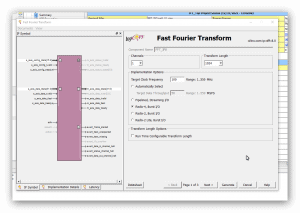
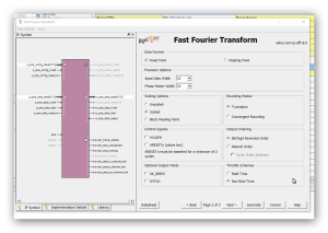
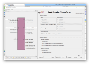
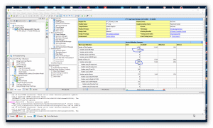
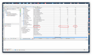
Cześć, jak wspomniałem wcześniej w wątku: Chciałbym porównać szybkość działania algorytmu FFT z użyciem "IP Core FFT" Xilinx'a. Mam zamiar wykonać próby na trzech zestawach FPGA (1024 próbki - 16 bit na próbkę - fixed point): 1) Elbert V.2 - Spartan3A (XC3S50A): brak bloków DSP i trzy sprzętowe układy mnożące 2) Mimas V.2 - Spartan6 (XC6SLX9) : 16 bloków DSP48 3) CMod A7-35 - Artix7 -(XC7A35T): 90 bloków DSP48 Z trzema różnymi częstotliwościami zegara układów FPGA. Rozpocząłem od projektu dla układu FPGA Spartan6(XC6SLX9 in CSG324 package) z zestawu MImas V.2: https://numato.com/product/mimas-v2-spartan-6-fpga-development-board-with-ddr-sdram/ Parametry IP Core FFT w wersji 8.0 Xilinx'a są tak dobrane tak, aby transformata FFT miała długość 1024 punkty i precyzję próbek 16-bit "fixed point" (z zegarem 100 MHz). Po ustawieniu parametrów IP Core jak jest przedstawione na kolejnych zrzutach ekranu: ekran 1 - długość transformaty 1024 punkty 1 kanał i opcja implementacji: "Radix-4, Burst I/O" (optymalizacja ze względu na czas wykonania(). ekran 2 - Precyzja 16-bit "scaled" ekran 3 - użycie "Block RAM", "Use 4-multipler structure" (optymalizacja z użyciem bloków DSP), "Arytmetyka Butterfly" z użyciem bloków CLB. Aby zorientować się jak działają konkretne wybrane opcje polecam przeczytać ten artykuł: https://www.allaboutcircuits.com/technical-articles/xilinx-fft-ip-core-fast-fourier-transform-software-walkthrough/ Po zakończeniu wyboru opcji dla "IP Core FFT V.8" i generacji jego modułów dodałem "top entity" (o nazwie: FFT_Top) w którym wywołuje(komponent) instancję IP Core FFT o nazwie " FFT_IP8". Na tym etapie jest to mi potrzebne wyłącznie w tym celu, aby móc uruchomić syntezę i implementację projektu w celu oszacowania liczby zasobów układu FPGA zużywanych przez projekt. I po zakończeniu fazy syntezy i implementacji można już podać liczbę podstawowych zużywanych zasobów: 1) Liczba przerzutników (FF) 1925 2) Liczba LUT 1468 3) Liczba użytych bloków DSP48 - 12 z 16 dostępnych (dla tej wersji układu Spartan6) Nie jest to mało - patrz zrzuty ekranu z ISE: Tutaj podaję kod głównego entity projektu (okazało się, że w przypadku tego IP Core jedyny wybór to język VHDL): ---------------------------------------------------------------------------------- -- Company: -- Engineer: -- -- Create Date: 13:32:16 12/31/2021 -- Design Name: -- Module Name: FFT_Top - Behavioral -- Project Name: -- Target Devices: -- Tool versions: -- Description: -- -- Dependencies: -- -- Revision: -- Revision 0.01 - File Created -- Additional Comments: -- ---------------------------------------------------------------------------------- library IEEE; use IEEE.STD_LOGIC_1164.ALL; -- Uncomment the following library declaration if using -- arithmetic functions with Signed or Unsigned values --use IEEE.NUMERIC_STD.ALL; -- Uncomment the following library declaration if instantiating -- any Xilinx primitives in this code. --library UNISIM; --use UNISIM.VComponents.all; entity FFT_Top is port ( aclk : in STD_LOGIC := 'X'; s_axis_config_tvalid : in STD_LOGIC := 'X'; s_axis_data_tvalid : in STD_LOGIC := 'X'; s_axis_data_tlast : in STD_LOGIC := 'X'; m_axis_data_tready : in STD_LOGIC := 'X'; s_axis_config_tready : out STD_LOGIC; s_axis_data_tready : out STD_LOGIC; m_axis_data_tvalid : out STD_LOGIC; m_axis_data_tlast : out STD_LOGIC; event_frame_started : out STD_LOGIC; event_tlast_unexpected : out STD_LOGIC; event_tlast_missing : out STD_LOGIC; event_status_channel_halt : out STD_LOGIC; event_data_in_channel_halt : out STD_LOGIC; event_data_out_channel_halt : out STD_LOGIC; s_axis_config_tdata : in STD_LOGIC_VECTOR ( 15 downto 0 ); s_axis_data_tdata : in STD_LOGIC_VECTOR ( 31 downto 0 ); m_axis_data_tdata : out STD_LOGIC_VECTOR ( 31 downto 0 ) ); end FFT_Top; architecture Behavioral of FFT_Top is ------------- Begin Cut here for COMPONENT Declaration ------ COMP_TAG COMPONENT FFT_IP8 PORT ( aclk : IN STD_LOGIC; s_axis_config_tdata : IN STD_LOGIC_VECTOR(15 DOWNTO 0); s_axis_config_tvalid : IN STD_LOGIC; s_axis_config_tready : OUT STD_LOGIC; s_axis_data_tdata : IN STD_LOGIC_VECTOR(31 DOWNTO 0); s_axis_data_tvalid : IN STD_LOGIC; s_axis_data_tready : OUT STD_LOGIC; s_axis_data_tlast : IN STD_LOGIC; m_axis_data_tdata : OUT STD_LOGIC_VECTOR(31 DOWNTO 0); m_axis_data_tvalid : OUT STD_LOGIC; m_axis_data_tready : IN STD_LOGIC; m_axis_data_tlast : OUT STD_LOGIC; event_frame_started : OUT STD_LOGIC; event_tlast_unexpected : OUT STD_LOGIC; event_tlast_missing : OUT STD_LOGIC; event_status_channel_halt : OUT STD_LOGIC; event_data_in_channel_halt : OUT STD_LOGIC; event_data_out_channel_halt : OUT STD_LOGIC ); END COMPONENT; -- COMP_TAG_END ------ End COMPONENT Declaration ------------ begin ------------- Begin Cut here for INSTANTIATION Template ----- INST_TAG FFT_1024_16 : FFT_IP8 PORT MAP ( aclk => aclk, s_axis_config_tdata => s_axis_config_tdata, s_axis_config_tvalid => s_axis_config_tvalid, s_axis_config_tready => s_axis_config_tready, s_axis_data_tdata => s_axis_data_tdata, s_axis_data_tvalid => s_axis_data_tvalid, s_axis_data_tready => s_axis_data_tready, s_axis_data_tlast => s_axis_data_tlast, m_axis_data_tdata => m_axis_data_tdata, m_axis_data_tvalid => m_axis_data_tvalid, m_axis_data_tready => m_axis_data_tready, m_axis_data_tlast => m_axis_data_tlast, event_frame_started => event_frame_started, event_tlast_unexpected => event_tlast_unexpected, event_tlast_missing => event_tlast_missing, event_status_channel_halt => event_status_channel_halt, event_data_in_channel_halt => event_data_in_channel_halt, event_data_out_channel_halt => event_data_out_channel_halt ); -- INST_TAG_END ------ End INSTANTIATION Template ------------ end Behavioral; Podczas generacji modułów "IP Core FFT V.8" został także utworzony test-bench, który zamierzam wykorzystać do pierwszych testów FFT - oto jego kod: --------------------------------------------------------------------------- -- -- (c) Copyright 2010 Xilinx, Inc. All rights reserved. -- -- This file contains confidential and proprietary information -- of Xilinx, Inc. and is protected under U.S. and -- international copyright and other intellectual property -- laws. -- -- DISCLAIMER -- This disclaimer is not a license and does not grant any -- rights to the materials distributed herewith. Except as -- otherwise provided in a valid license issued to you by -- Xilinx, and to the maximum extent permitted by applicable -- law: (1) THESE MATERIALS ARE MADE AVAILABLE "AS IS" AND -- WITH ALL FAULTS, AND XILINX HEREBY DISCLAIMS ALL WARRANTIES -- AND CONDITIONS, EXPRESS, IMPLIED, OR STATUTORY, INCLUDING -- BUT NOT LIMITED TO WARRANTIES OF MERCHANTABILITY, NON- -- INFRINGEMENT, OR FITNESS FOR ANY PARTICULAR PURPOSE; and -- (2) Xilinx shall not be liable (whether in contract or tort, -- including negligence, or under any other theory of -- liability) for any loss or damage of any kind or nature -- related to, arising under or in connection with these -- materials, including for any direct, or any indirect, -- special, incidental, or consequential loss or damage -- (including loss of data, profits, goodwill, or any type of -- loss or damage suffered as a result of any action brought -- by a third party) even if such damage or loss was -- reasonably foreseeable or Xilinx had been advised of the -- possibility of the same. -- -- CRITICAL APPLICATIONS -- Xilinx products are not designed or intended to be fail- -- safe, or for use in any application requiring fail-safe -- performance, such as life-support or safety devices or -- systems, Class III medical devices, nuclear facilities, -- applications related to the deployment of airbags, or any -- other applications that could lead to death, personal -- injury, or severe property or environmental damage -- (individually and collectively, "Critical -- Applications"). Customer assumes the sole risk and -- liability of any use of Xilinx products in Critical -- Applications, subject only to applicable laws and -- regulations governing limitations on product liability. -- -- THIS COPYRIGHT NOTICE AND DISCLAIMER MUST BE RETAINED AS -- PART OF THIS FILE AT ALL TIMES. -- --------------------------------------------------------------------------- -- Description: -- This is an example testbench for the Fast Fourier Transform (FFT) LogiCORE module. -- The testbench has been generated by the Xilinx CORE Generator software -- to accompany the netlist you have generated. -- -- This testbench is for demonstration purposes only. See note below for -- instructions on how to use it with the netlist created for your core. -- -- See the FFT datasheet for further information about this core. -- --------------------------------------------------------------------------- -- Using this testbench -- -- This testbench instantiates your generated FFT core named "FFT_IP8". -- -- If your CORE Generator project options were set to generate a structural -- model, a VHDL netlist named FFT_IP8.vhd was generated. -- If this file is not present, execute the following command in the directory -- containing your CORE Generator output files, to create a VHDL netlist: -- -- netgen -sim -ofmt vhdl FFT_IP8.ngc FFT_IP8.vhd -- -- Compile FFT_IP8.vhd into the work library. See your simulator -- documentation for more information on how to do this. -- --------------------------------------------------------------------------- library ieee; use ieee.std_logic_1164.all; use ieee.numeric_std.all; use ieee.math_real.all; entity tb_FFT_IP8 is end tb_FFT_IP8; architecture tb of tb_FFT_IP8 is ----------------------------------------------------------------------- -- Timing constants ----------------------------------------------------------------------- constant CLOCK_PERIOD : time := 100 ns; constant T_HOLD : time := 10 ns; constant T_STROBE : time := CLOCK_PERIOD - (1 ns); ----------------------------------------------------------------------- -- DUT signals ----------------------------------------------------------------------- -- General signals signal aclk : std_logic := '0'; -- the master clock -- Config slave channel signals signal s_axis_config_tvalid : std_logic := '0'; -- payload is valid signal s_axis_config_tready : std_logic := '1'; -- slave is ready signal s_axis_config_tdata : std_logic_vector(15 downto 0) := (others => '0'); -- data payload -- Data slave channel signals signal s_axis_data_tvalid : std_logic := '0'; -- payload is valid signal s_axis_data_tready : std_logic := '1'; -- slave is ready signal s_axis_data_tdata : std_logic_vector(31 downto 0) := (others => '0'); -- data payload signal s_axis_data_tlast : std_logic := '0'; -- indicates end of packet -- Data master channel signals signal m_axis_data_tvalid : std_logic := '0'; -- payload is valid signal m_axis_data_tready : std_logic := '1'; -- slave is ready signal m_axis_data_tdata : std_logic_vector(31 downto 0) := (others => '0'); -- data payload signal m_axis_data_tlast : std_logic := '0'; -- indicates end of packet -- Event signals signal event_frame_started : std_logic := '0'; signal event_tlast_unexpected : std_logic := '0'; signal event_tlast_missing : std_logic := '0'; signal event_status_channel_halt : std_logic := '0'; signal event_data_in_channel_halt : std_logic := '0'; signal event_data_out_channel_halt : std_logic := '0'; ----------------------------------------------------------------------- -- Aliases for AXI channel TDATA and TUSER fields -- These are a convenience for viewing data in a simulator waveform viewer. -- If using ModelSim or Questa, add "-voptargs=+acc=n" to the vsim command -- to prevent the simulator optimizing away these signals. ----------------------------------------------------------------------- -- Config slave channel alias signals signal s_axis_config_tdata_fwd_inv : std_logic := '0'; -- forward or inverse signal s_axis_config_tdata_scale_sch : std_logic_vector(9 downto 0) := (others => '0'); -- scaling schedule -- Data slave channel alias signals signal s_axis_data_tdata_re : std_logic_vector(15 downto 0) := (others => '0'); -- real data signal s_axis_data_tdata_im : std_logic_vector(15 downto 0) := (others => '0'); -- imaginary data -- Data master channel alias signals signal m_axis_data_tdata_re : std_logic_vector(15 downto 0) := (others => '0'); -- real data signal m_axis_data_tdata_im : std_logic_vector(15 downto 0) := (others => '0'); -- imaginary data ----------------------------------------------------------------------- -- Constants, types and functions to create input data ----------------------------------------------------------------------- constant IP_WIDTH : integer := 16; constant MAX_SAMPLES : integer := 2**10; -- maximum number of samples in a frame type T_IP_SAMPLE is record re : std_logic_vector(IP_WIDTH-1 downto 0); im : std_logic_vector(IP_WIDTH-1 downto 0); end record; type T_IP_TABLE is array (0 to MAX_SAMPLES-1) of T_IP_SAMPLE; -- Zeroed input data table, for reset and initialization constant IP_TABLE_CLEAR : T_IP_TABLE := (others => (re => (others => '0'), im => (others => '0'))); -- Function to generate input data table -- Data is a complex sinusoid exp(-jwt) with a frequency 2.6 times the frame size -- added to another with a lower magnitude and a higher frequency function create_ip_table return T_IP_TABLE is variable result : T_IP_TABLE; variable theta : real; variable theta2 : real; variable re_real : real; variable im_real : real; variable re_int : integer; variable im_int : integer; begin for i in 0 to MAX_SAMPLES-1 loop theta := real(i) / real(MAX_SAMPLES) * 2.6 * 2.0 * MATH_PI; re_real := cos(-theta); im_real := sin(-theta); theta2 := real(i) / real(MAX_SAMPLES) * 23.2 * 2.0 * MATH_PI; re_real := re_real + (cos(-theta2) / 4.0); im_real := im_real + (sin(-theta2) / 4.0); re_int := integer(round(re_real * real(2**(IP_WIDTH-2)))); im_int := integer(round(im_real * real(2**(IP_WIDTH-2)))); result(i).re := std_logic_vector(to_signed(re_int, IP_WIDTH)); result(i).im := std_logic_vector(to_signed(im_int, IP_WIDTH)); end loop; return result; end function create_ip_table; -- Call the function to create the input data constant IP_DATA : T_IP_TABLE := create_ip_table; ----------------------------------------------------------------------- -- Testbench signals ----------------------------------------------------------------------- -- Communication between processes regarding DUT configuration type T_DO_CONFIG is (NONE, IMMEDIATE, AFTER_START, DONE); shared variable do_config : T_DO_CONFIG := NONE; -- instruction for driving config slave channel type T_CFG_FWD_INV is (FWD, INV); signal cfg_fwd_inv : T_CFG_FWD_INV := FWD; type T_CFG_SCALE_SCH is (ZERO, DEFAULT); signal cfg_scale_sch : T_CFG_SCALE_SCH := DEFAULT; -- Recording output data, for reuse as input data signal op_sample : integer := 0; -- output sample number signal op_sample_first : std_logic := '1'; -- indicates first output sample of a frame signal ip_frame : integer := 0; -- input / configuration frame number signal op_data : T_IP_TABLE := IP_TABLE_CLEAR; -- recorded output data signal op_frame : integer := 0; -- output frame number (incremented at end of frame output) begin ----------------------------------------------------------------------- -- Instantiate the DUT ----------------------------------------------------------------------- dut : entity work.FFT_IP8 port map ( aclk => aclk, s_axis_config_tvalid => s_axis_config_tvalid, s_axis_config_tready => s_axis_config_tready, s_axis_config_tdata => s_axis_config_tdata, s_axis_data_tvalid => s_axis_data_tvalid, s_axis_data_tready => s_axis_data_tready, s_axis_data_tdata => s_axis_data_tdata, s_axis_data_tlast => s_axis_data_tlast, m_axis_data_tvalid => m_axis_data_tvalid, m_axis_data_tready => m_axis_data_tready, m_axis_data_tdata => m_axis_data_tdata, m_axis_data_tlast => m_axis_data_tlast, event_frame_started => event_frame_started, event_tlast_unexpected => event_tlast_unexpected, event_tlast_missing => event_tlast_missing, event_status_channel_halt => event_status_channel_halt, event_data_in_channel_halt => event_data_in_channel_halt, event_data_out_channel_halt => event_data_out_channel_halt ); ----------------------------------------------------------------------- -- Generate clock ----------------------------------------------------------------------- clock_gen : process begin aclk <= '0'; wait for CLOCK_PERIOD; loop aclk <= '0'; wait for CLOCK_PERIOD/2; aclk <= '1'; wait for CLOCK_PERIOD/2; end loop; end process clock_gen; ----------------------------------------------------------------------- -- Generate data slave channel inputs ----------------------------------------------------------------------- data_stimuli : process -- Variables for random number generation variable seed1, seed2 : positive; variable rand : real; -- Procedure to drive an input sample with specific data -- data is the data value to drive on the tdata signal -- last is the bit value to drive on the tlast signal -- valid_mode defines how to drive TVALID: 0 = TVALID always high, 1 = TVALID low occasionally procedure drive_sample ( data : std_logic_vector(31 downto 0); last : std_logic; valid_mode : integer := 0 ) is begin s_axis_data_tdata <= data; s_axis_data_tlast <= last; if valid_mode = 1 then uniform(seed1, seed2, rand); -- generate random number if rand < 0.25 then s_axis_data_tvalid <= '0'; uniform(seed1, seed2, rand); -- generate another random number wait for CLOCK_PERIOD * integer(round(rand * 4.0)); -- hold TVALID low for up to 4 cycles s_axis_data_tvalid <= '1'; -- now assert TVALID else s_axis_data_tvalid <= '1'; end if; else s_axis_data_tvalid <= '1'; end if; loop wait until rising_edge(aclk); exit when s_axis_data_tready = '1'; end loop; wait for T_HOLD; s_axis_data_tvalid <= '0'; end procedure drive_sample; -- Procedure to drive an input frame with a table of data -- data is the data table containing input data -- valid_mode defines how to drive TVALID: 0 = TVALID always high, 1 = TVALID low occasionally procedure drive_frame ( data : T_IP_TABLE; valid_mode : integer := 0 ) is variable samples : integer; variable index : integer; variable sample_data : std_logic_vector(31 downto 0); variable sample_last : std_logic; begin samples := data'length; index := 0; while index < data'length loop -- Look up sample data in data table, construct TDATA value sample_data(15 downto 0) := data(index).re; -- real data sample_data(31 downto 16) := data(index).im; -- imaginary data -- Construct TLAST's value index := index + 1; if index >= data'length then sample_last := '1'; else sample_last := '0'; end if; -- Drive the sample drive_sample(sample_data, sample_last, valid_mode); end loop; end procedure drive_frame; variable op_data_saved : T_IP_TABLE; -- to save a copy of recorded output data begin -- Drive inputs T_HOLD time after rising edge of clock wait until rising_edge(aclk); wait for T_HOLD; -- Drive a frame of input data ip_frame <= 1; drive_frame(IP_DATA); -- Allow the result to emerge wait until m_axis_data_tlast = '1'; wait until rising_edge(aclk); wait for T_HOLD; -- Take a copy of the result, to use later as input op_data_saved := op_data; -- Now perform an inverse transform on the result to get back to the original input -- Set up the configuration (config_stimuli process handles the config slave channel) ip_frame <= 2; cfg_fwd_inv <= INV; do_config := IMMEDIATE; while do_config /= DONE loop wait until rising_edge(aclk); end loop; wait for T_HOLD; -- Configuration is done. Set up another configuration to return to forward transforms, -- and make the configuration occur as soon as the next frame has begun ip_frame <= 3; cfg_fwd_inv <= FWD; do_config := AFTER_START; -- Now drive the input data, using the output data of the last frame drive_frame(op_data); wait until m_axis_data_tlast = '1'; wait until rising_edge(aclk); wait for T_HOLD; -- The frame is complete, and the configuration to forward transforms has already been done, -- so drive the input data, using the output data of the last frame, -- which is the same as the original input (excepting scaling and finite precision effects). -- This time, deassert the data slave channel TVALID occasionally to illustrate AXI handshaking effects: -- as the core is configured to use Non Real Time throttle scheme, it will pause when TVALID is low. drive_frame(op_data, 1); -- During the output of this frame, deassert the data master channel TREADY occasionally: -- as the core is configured to use Non Real Time throttle scheme, it will pause when TREADY is low. wait until m_axis_data_tvalid = '1'; wait until rising_edge(aclk); while m_axis_data_tlast /= '1' loop wait for T_HOLD; uniform(seed1, seed2, rand); -- generate random number if rand < 0.25 then m_axis_data_tready <= '0'; else m_axis_data_tready <= '1'; end if; wait until rising_edge(aclk); end loop; wait for T_HOLD; m_axis_data_tready <= '1'; wait for CLOCK_PERIOD; -- Now run 4 back-to-back transforms, as quickly as possible. -- First queue up 2 configurations: these will be applied successively over the next 2 transforms. -- 1st configuration ip_frame <= 4; cfg_fwd_inv <= FWD; -- forward transform cfg_scale_sch <= DEFAULT; -- default scaling schedule do_config := IMMEDIATE; while do_config /= DONE loop wait until rising_edge(aclk); end loop; wait for T_HOLD; -- 2nd configuration: same as 1st, except: ip_frame <= 5; cfg_fwd_inv <= INV; -- inverse transform cfg_scale_sch <= ZERO; -- no scaling do_config := IMMEDIATE; while do_config /= DONE loop wait until rising_edge(aclk); end loop; wait for T_HOLD; -- Drive the 1st data frame drive_frame(IP_DATA); -- Request a 3rd configuration, to be sent after 2nd data frame starts ip_frame <= 6; cfg_fwd_inv <= FWD; -- forward transform cfg_scale_sch <= ZERO; -- no scaling do_config := AFTER_START; -- Drive the 2nd data frame drive_frame(op_data_saved); -- Request a 4th configuration, to be sent after 3rd data frame starts: same as 3rd, except: ip_frame <= 7; cfg_fwd_inv <= INV; -- inverse transform cfg_scale_sch <= DEFAULT; -- default scaling schedule do_config := AFTER_START; -- Drive the 3rd data frame drive_frame(IP_DATA); -- Drive the 4th data frame drive_frame(op_data_saved); -- Wait until all the output data from all frames has been produced wait until op_frame = 7; wait for CLOCK_PERIOD * 10; -- End of test report "Not a real failure. Simulation finished successfully." severity failure; wait; end process data_stimuli; ----------------------------------------------------------------------- -- Generate config slave channel inputs ----------------------------------------------------------------------- config_stimuli : process variable scale_sch : std_logic_vector(9 downto 0); begin -- Drive a configuration when requested by data_stimuli process wait until rising_edge(aclk); while do_config = NONE or do_config = DONE loop wait until rising_edge(aclk); end loop; -- If the configuration is requested to occur after the next frame starts, wait for that event if do_config = AFTER_START then wait until event_frame_started = '1'; wait until rising_edge(aclk); end if; -- Drive inputs T_HOLD time after rising edge of clock wait for T_HOLD; -- Construct the config slave channel TDATA signal s_axis_config_tdata <= (others => '0'); -- clear unused bits -- Format the transform direction if cfg_fwd_inv = FWD then s_axis_config_tdata(0) <= '1'; -- forward elsif cfg_fwd_inv = INV then s_axis_config_tdata(0) <= '0'; -- inverse end if; -- Format the scaling schedule if cfg_scale_sch = ZERO then -- no scaling scale_sch := (others => '0'); elsif cfg_scale_sch = DEFAULT then -- default scaling, for largest magnitude output with no overflow guaranteed scale_sch(1 downto 0) := "11"; -- largest scaling at first stage for s in 2 to 5 loop scale_sch(s*2-1 downto s*2-2) := "10"; -- less scaling at later stages end loop; end if; s_axis_config_tdata(10 downto 1) <= scale_sch; -- Drive the transaction on the config slave channel s_axis_config_tvalid <= '1'; loop wait until rising_edge(aclk); exit when s_axis_config_tready = '1'; end loop; wait for T_HOLD; s_axis_config_tvalid <= '0'; -- Tell the data_stimuli process that the configuration has been done do_config := DONE; end process config_stimuli; ----------------------------------------------------------------------- -- Record outputs, to use later as inputs for another frame ----------------------------------------------------------------------- record_outputs : process (aclk) -- Function to digit-reverse an integer, to convert output to input ordering function digit_reverse_int ( fwd, width : integer ) return integer is variable rev : integer; variable fwd_slv : std_logic_vector(width-1 downto 0); variable rev_slv : std_logic_vector(width-1 downto 0); begin fwd_slv := std_logic_vector(to_unsigned(fwd, width)); for i in 0 to width/2-1 loop -- reverse in digit groups (2 bits at a time) rev_slv(i*2+1 downto i*2) := fwd_slv(width-i*2-1 downto width-i*2-2); end loop; if width mod 2 = 1 then -- width is odd: LSB moves to MSB rev_slv(width-1) := fwd_slv(0); end if; rev := to_integer(unsigned(rev_slv)); return rev; end function digit_reverse_int; variable index : integer := 0; begin if rising_edge(aclk) then if m_axis_data_tvalid = '1' and m_axis_data_tready = '1' then -- Record output data such that it can be used as input data index := op_sample; -- Digit-reverse output sample number, to get actual sample index as outputs are in digit-reversed order index := digit_reverse_int(index, 10); op_data(index).re <= m_axis_data_tdata(15 downto 0); op_data(index).im <= m_axis_data_tdata(31 downto 16); -- Increment output sample counter if m_axis_data_tlast = '1' then -- end of output frame: reset sample counter and increment frame counter op_sample <= 0; op_frame <= op_frame + 1; op_sample_first <= '1'; -- for next output frame else op_sample_first <= '0'; op_sample <= op_sample + 1; end if; end if; end if; end process record_outputs; ----------------------------------------------------------------------- -- Check outputs ----------------------------------------------------------------------- check_outputs : process variable check_ok : boolean := true; -- Previous values of data master channel signals variable m_data_tvalid_prev : std_logic := '0'; variable m_data_tready_prev : std_logic := '0'; variable m_data_tdata_prev : std_logic_vector(31 downto 0) := (others => '0'); begin -- Check outputs T_STROBE time after rising edge of clock wait until rising_edge(aclk); wait for T_STROBE; -- Do not check the output payload values, as this requires a numerical model -- which would make this demonstration testbench unwieldy. -- Instead, check the protocol of the data master channel: -- check that the payload is valid (not X) when TVALID is high -- and check that the payload does not change while TVALID is high until TREADY goes high if m_axis_data_tvalid = '1' then if is_x(m_axis_data_tdata) then report "ERROR: m_axis_data_tdata is invalid when m_axis_data_tvalid is high" severity error; check_ok := false; end if; if m_data_tvalid_prev = '1' and m_data_tready_prev = '0' then -- payload must be the same as last cycle if m_axis_data_tdata /= m_data_tdata_prev then report "ERROR: m_axis_data_tdata changed while m_axis_data_tvalid was high and m_axis_data_tready was low" severity error; check_ok := false; end if; end if; end if; assert check_ok report "ERROR: terminating test with failures." severity failure; -- Record payload values for checking next clock cycle if check_ok then m_data_tvalid_prev := m_axis_data_tvalid; m_data_tready_prev := m_axis_data_tready; m_data_tdata_prev := m_axis_data_tdata; end if; end process check_outputs; ----------------------------------------------------------------------- -- Assign TDATA / TUSER fields to aliases, for easy simulator waveform viewing ----------------------------------------------------------------------- -- Config slave channel alias signals s_axis_config_tdata_fwd_inv <= s_axis_config_tdata(0); s_axis_config_tdata_scale_sch <= s_axis_config_tdata(10 downto 1); -- Data slave channel alias signals s_axis_data_tdata_re <= s_axis_data_tdata(15 downto 0); s_axis_data_tdata_im <= s_axis_data_tdata(31 downto 16); -- Data master channel alias signals m_axis_data_tdata_re <= m_axis_data_tdata(15 downto 0); m_axis_data_tdata_im <= m_axis_data_tdata(31 downto 16); end tb; A tutaj spakowany kod projektu dla "ISE 14.7 Webpack": FFT_IPCore8_01.zip Zachęcam do własnych prób z tym projektem. Ciąg dalszy nastąpi ... Pozdrawiam
-
Witam, Właśnie rusza projekt, który ma umożliwiać zdalne nauczanie zagadnień z mechatroniki i przetwarzania sygnałów. Idea jest taka, aby każdy uczeń/student miał w domu swoje własne stanowisko ze szkoły, sam rejestrował dane, a następnie, żeby nauczył się je przetwarzać w chmurze. Na chwilę obecną szukane są pomysły, np.: 1) użytkownik sam zbiera dane drganiowe z kilkudziesięciu cykli prania, a dostarczony generator dodaje sygnały powolnego uszkodzenia łożyska, generując zbiór Big Data. Następnie, użytkownik zgodnie z instrukcją opracowuje w chmurze algorytm Novelty Detection (np.sieć LSTM). 2) w zestawie jest obudowa łożyska, która jest elektromechanicznie wzbudzana z wykorzystaniem Arduino/Raspberry Pi. Drugi układ Arduino/Raspberry Pi rejestruje odpowiedź na wymuszenie. Następnie, estymowana funkcja odpowiedzi częstotliwościowej (FRF) jest wykorzystywana jako część stochastyczna sygnału syntetycznego rozwoju uszkodzenia łożyska tocznego. Na jej podstawie budowany jest zbiór Big Data, który bardzo wiernie odzwierciedla sygnały rzeczywiste. Dane są zbierane od wielu użytkowników i są użyte w procesie uczenia maszynowego w chmurze. 3) oczywiście, takie zestawy WYMUSZENIE/REJESTRACJA same w sobie pozwalają na analizę wpływu rodzaju wymuszenia na estymowaną FRF 4) Dalsze pomysły?! Pozdrawiam, Ajab00
-
- DSP
- Raspberry Pi
-
(i 3 więcej)
Tagi:


