Skocz do zawartości

Robot balansujący, problem przy komunIkacji BT


kryska016

Pomocna odpowiedź

Witam Wszystkich,
Od długiego już czasu pracuję nad robotem balansującym. Do tego czasu szło w miarę dobrze lecz ostatnie kilkanaście dni stoję w miejscu gdyż napotkałem problem. Może napiszę wszystko od początku:

Gdy zaczynałem budowę robota początkowo miałem zamiar napisać program sam lecz po nieudanych próbach postanowiłem skorzystać z projektów dostępnych w internecie. Kod zaczerpnąłem z projektu który znajduje się w linku: http://www.brokking.net/yabr_main.html

Początkowo uznałem że zastosuję taką samą komunikację, lecz po próbach z powodu częstych problemów z komunikacją ( wystarczyło że robot wyjechał poza pokój i wjeżdżał za ścianę od razu połączenie się zrywało) zrezygnowałem z tego pomysłu i postanowiłem przepisać kod na komunikację przez BT i sterowanie robota z poziomu telefonu. Zanim jeszcze przepisałem kod sprawdziłem jakie wartości przyjmuje received_byte w zależności od położenia joysticka. Następnie za pomocą funkcji if ustawiam odpowiednią wartość received_byte w zależności od wartości inByte (wartość otrzymywana z BT wysłana z aplikacji "Arduino Bluetooth RC Car")

I tu pojawia się problem.

Zanim połączę telefon z modułem BT robot bezproblemowo utrzymuje równowagę a silniki pracują bez zarzutu. Natomiast w momencie nawiązania połączenia przez moduł BT silniki nagle zaczynają dziwnie chodzić ( tak jakby gubiły kroki) Robot utrzymuje równowagę i jeździ lecz problemem są niepoprawnie działające silniki.

Elementy składowe robota:

mpu 6050

2x silnik nema 17

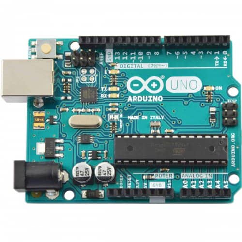
Arduino UNO

2x Pololu A4988

HC 05

Poniżej zamieszczam kod programu robota. Przypuszczam że tutaj może leżeć problem ponieważ w programowaniu nie mam za dużego doświadczenia.

#include <SoftwareSerial.h>
#include <Wire.h>                                            //Include the Wire.h library so we can communicate with the gyro
SoftwareSerial BT(10,11);
//#define B00000011
//#define B00000111
//#define B00001011
//#define B00000001  
//#define B00000010
//#define B00000110
//#define B00000101
//#define B00001010
//#define B00001001
int gyro_address = 0x68;                                     //MPU-6050 I2C address (0x68 or 0x69)
int acc_calibration_value = -529;                            //Enter the accelerometer calibration value

//Various settings
float pid_p_gain = 15;                                       //Gain setting for the P-controller (15)
float pid_i_gain = 1.5;                                      //Gain setting for the I-controller (1.5)
float pid_d_gain = 30;                                       //Gain setting for the D-controller (30)
float turning_speed = 40;                                    //Turning speed (20)
float max_target_speed = 200;                                //Max target speed (100)

///////////////////////////////////////////////////////////////////////////////////////////////////////////////////////////////////////
//Declaring global variables
///////////////////////////////////////////////////////////////////////////////////////////////////////////////////////////////////////
byte start, received_byte, low_bat;

int left_motor, throttle_left_motor, throttle_counter_left_motor, throttle_left_motor_memory;
int right_motor, throttle_right_motor, throttle_counter_right_motor, throttle_right_motor_memory;
int battery_voltage;
int receive_counter;
int gyro_pitch_data_raw, gyro_yaw_data_raw, accelerometer_data_raw;

long gyro_yaw_calibration_value, gyro_pitch_calibration_value;

unsigned long loop_timer;

float angle_gyro, angle_acc, angle, self_balance_pid_setpoint;
float pid_error_temp, pid_i_mem, pid_setpoint, gyro_input, pid_output, pid_last_d_error;
float pid_output_left, pid_output_right;

///////////////////////////////////////////////////////////////////////////////////////////////////////////////////////////////////////
//Setup basic functions
///////////////////////////////////////////////////////////////////////////////////////////////////////////////////////////////////////
void setup(){
                                                    //Set the I2C clock speed to 400kHz
Serial.begin(9600);
 while (!Serial){;} 
BT.begin(9600);

// Serial.begin(9600);                                                       //Start the serial port at 9600 kbps
// Wire.begin();                                                             //Start the I2C bus as master
 //TWBR = 12;           
 //To create a variable pulse for controlling the stepper motors a timer is created that will execute a piece of code (subroutine) every 20us
 //This subroutine is called TIMER2_COMPA_vect
 TCCR2A = 0;                                                               //Make sure that the TCCR2A register is set to zero
 TCCR2B = 0;                                                               //Make sure that the TCCR2A register is set to zero
 TIMSK2 |= (1 << OCIE2A);                                                  //Set the interupt enable bit OCIE2A in the TIMSK2 register
 TCCR2B |= (1 << CS21);                                                    //Set the CS21 bit in the TCCRB register to set the prescaler to 8
 OCR2A = 18;                                                               //The compare register is set to 39 => 20us / (1s / (16.000.000MHz / 8)) - 1
 TCCR2A |= (1 << WGM21);                                                   //Set counter 2 to CTC (clear timer on compare) mode

 //By default the MPU-6050 sleeps. So we have to wake it up.
 Wire.beginTransmission(gyro_address);                                     //Start communication with the address found during search.
 Wire.write(0x6B);                                                         //We want to write to the PWR_MGMT_1 register (6B hex)
 Wire.write(0x00);                                                         //Set the register bits as 00000000 to activate the gyro
 Wire.endTransmission();                                                   //End the transmission with the gyro.
 //Set the full scale of the gyro to +/- 250 degrees per second
 Wire.beginTransmission(gyro_address);                                     //Start communication with the address found during search.
 Wire.write(0x1B);                                                         //We want to write to the GYRO_CONFIG register (1B hex)
 Wire.write(0x00);                                                         //Set the register bits as 00000000 (250dps full scale)
 Wire.endTransmission();                                                   //End the transmission with the gyro
 //Set the full scale of the accelerometer to +/- 4g.
 Wire.beginTransmission(gyro_address);                                     //Start communication with the address found during search.
 Wire.write(0x1C);                                                         //We want to write to the ACCEL_CONFIG register (1A hex)
 Wire.write(0x08);                                                         //Set the register bits as 00001000 (+/- 4g full scale range)
 Wire.endTransmission();                                                   //End the transmission with the gyro
 //Set some filtering to improve the raw data.
 Wire.beginTransmission(gyro_address);                                     //Start communication with the address found during search
 Wire.write(0x1A);                                                         //We want to write to the CONFIG register (1A hex)
 Wire.write(0x03);                                                         //Set the register bits as 00000011 (Set Digital Low Pass Filter to ~43Hz)
 Wire.endTransmission();                                                   //End the transmission with the gyro 

 pinMode(2, OUTPUT);                                                       //Configure digital poort 2 as output
 pinMode(3, OUTPUT);                                                       //Configure digital poort 3 as output
 pinMode(4, OUTPUT);                                                       //Configure digital poort 4 as output
 pinMode(5, OUTPUT);                                                       //Configure digital poort 5 as output
 pinMode(13, OUTPUT);                                                      //Configure digital poort 6 as output

 for(receive_counter = 0; receive_counter < 500; receive_counter++){       //Create 500 loops
   if(receive_counter % 15 == 0)digitalWrite(13, !digitalRead(13));        //Change the state of the LED every 15 loops to make the LED blink fast
   Wire.beginTransmission(gyro_address);                                   //Start communication with the gyro
   Wire.write(0x43);                                                       //Start reading the Who_am_I register 75h
   Wire.endTransmission();                                                 //End the transmission
   Wire.requestFrom(gyro_address, 4);                                      //Request 2 bytes from the gyro
   gyro_yaw_calibration_value += Wire.read()<<8|Wire.read();               //Combine the two bytes to make one integer
   gyro_pitch_calibration_value += Wire.read()<<8|Wire.read();             //Combine the two bytes to make one integer
   delayMicroseconds(3700);                                                //Wait for 3700 microseconds to simulate the main program loop time
 }
 gyro_pitch_calibration_value /= 500;                                      //Divide the total value by 500 to get the avarage gyro offset
 gyro_yaw_calibration_value /= 500;                                        //Divide the total value by 500 to get the avarage gyro offset

 loop_timer = micros() + 4000;                                             //Set the loop_timer variable at the next end loop time

}

///////////////////////////////////////////////////////////////////////////////////////////////////////////////////////////////////////
//Main program loop
///////////////////////////////////////////////////////////////////////////////////////////////////////////////////////////////////////
void loop(){

// Serial.println(received_byte);
   while (BT.available() >= 0) {

 //if(Serial.available()){                                                   //If there is serial data available
   //received_byte = Serial.read();                                          //Load the received serial data in the received_byte variable
 //  receive_counter = 0;                                                    //Reset the receive_counter variable
//}
 //if(receive_counter <= 30)receive_counter ++;                              //The received byte will be valid for 25 program loops (100 milliseconds)
 //else received_byte = 0x00;                                                //After 100 milliseconds the received byte is deleted

 //Load the battery voltage to the battery_voltage variable.
 //85 is the voltage compensation for the diode.
 //Resistor voltage divider => (3.3k + 3.3k)/2.2k = 2.5
 //12.5V equals ~5V @ Analog 0.
 //12.5V equals 1023 analogRead(0).
 //1250 / 1023 = 1.222.
 //The variable battery_voltage holds 1050 if the battery voltage is 10.5V.
 battery_voltage = (analogRead(0) * 1.222) + 85;
  battery_voltage = (1023 * 1.222) + 85;
 if(battery_voltage < 1050 && battery_voltage > 800){                      //If batteryvoltage is below 10.5V and higher than 8.0V
   digitalWrite(13, HIGH);                                                 //Turn on the led if battery voltage is to low
   low_bat = 1;                                                            //Set the low_bat variable to 1
 }

 ///////////////////////////////////////////////////////////////////////////////////////////////////////////////////////////////////////
 //Angle calculations
 ///////////////////////////////////////////////////////////////////////////////////////////////////////////////////////////////////////
 Wire.beginTransmission(gyro_address);                                     //Start communication with the gyro
 Wire.write(0x3F);                                                         //Start reading at register 3F
 Wire.endTransmission();                                                   //End the transmission
 Wire.requestFrom(gyro_address, 2);                                        //Request 2 bytes from the gyro
 accelerometer_data_raw = Wire.read()<<8|Wire.read();                      //Combine the two bytes to make one integer
 accelerometer_data_raw += acc_calibration_value;                          //Add the accelerometer calibration value
 if(accelerometer_data_raw > 8200)accelerometer_data_raw = 8200;           //Prevent division by zero by limiting the acc data to +/-8200;
 if(accelerometer_data_raw < -8200)accelerometer_data_raw = -8200;         //Prevent division by zero by limiting the acc data to +/-8200;

 angle_acc = asin((float)accelerometer_data_raw/8200.0)* 57.296;           //Calculate the current angle according to the accelerometer

 if(start == 0 && angle_acc > -0.5&& angle_acc < 0.5){                     //If the accelerometer angle is almost 0
   angle_gyro = angle_acc;                                                 //Load the accelerometer angle in the angle_gyro variable
   start = 1;                                                              //Set the start variable to start the PID controller
 }

 Wire.beginTransmission(gyro_address);                                     //Start communication with the gyro
 Wire.write(0x43);                                                         //Start reading at register 43
 Wire.endTransmission();                                                   //End the transmission
 Wire.requestFrom(gyro_address, 4);                                        //Request 4 bytes from the gyro
 gyro_yaw_data_raw = Wire.read()<<8|Wire.read();                           //Combine the two bytes to make one integer
 gyro_pitch_data_raw = Wire.read()<<8|Wire.read();                         //Combine the two bytes to make one integer

 gyro_pitch_data_raw -= gyro_pitch_calibration_value;                      //Add the gyro calibration value
 angle_gyro += gyro_pitch_data_raw * 0.000031;                             //Calculate the traveled during this loop angle and add this to the angle_gyro variable

 ///////////////////////////////////////////////////////////////////////////////////////////////////////////////////////////////////////
 //MPU-6050 offset compensation
 ///////////////////////////////////////////////////////////////////////////////////////////////////////////////////////////////////////
 //Not every gyro is mounted 100% level with the axis of the robot. This can be cause by misalignments during manufacturing of the breakout board. 
 //As a result the robot will not rotate at the exact same spot and start to make larger and larger circles.
 //To compensate for this behavior a VERY SMALL angle compensation is needed when the robot is rotating.
 //Try 0.0000003 or -0.0000003 first to see if there is any improvement.

 gyro_yaw_data_raw -= gyro_yaw_calibration_value;                          //Add the gyro calibration value
 //Uncomment the following line to make the compensation active
 //angle_gyro -= gyro_yaw_data_raw * 0.0000003;                            //Compensate the gyro offset when the robot is rotating

 angle_gyro = angle_gyro * 0.9996 + angle_acc * 0.0004;                    //Correct the drift of the gyro angle with the accelerometer angle

 ///////////////////////////////////////////////////////////////////////////////////////////////////////////////////////////////////////
 //PID controller calculations
 ///////////////////////////////////////////////////////////////////////////////////////////////////////////////////////////////////////
 //The balancing robot is angle driven. First the difference between the desired angel (setpoint) and actual angle (process value)
 //is calculated. The self_balance_pid_setpoint variable is automatically changed to make sure that the robot stays balanced all the time.
 //The (pid_setpoint - pid_output * 0.015) part functions as a brake function.
 pid_error_temp = angle_gyro - self_balance_pid_setpoint - pid_setpoint;
 if(pid_output > 10 || pid_output < -10)pid_error_temp += pid_output * 0.015 ;

 pid_i_mem += pid_i_gain * pid_error_temp;                                 //Calculate the I-controller value and add it to the pid_i_mem variable
 if(pid_i_mem > 400)pid_i_mem = 400;                                       //Limit the I-controller to the maximum controller output
 else if(pid_i_mem < -400)pid_i_mem = -400;
 //Calculate the PID output value
 pid_output = pid_p_gain * pid_error_temp + pid_i_mem + pid_d_gain * (pid_error_temp - pid_last_d_error);
 if(pid_output > 400)pid_output = 400;                                     //Limit the PI-controller to the maximum controller output
 else if(pid_output < -400)pid_output = -400;

 pid_last_d_error = pid_error_temp;                                        //Store the error for the next loop

 if(pid_output < 5 && pid_output > -5)pid_output = 0;                      //Create a dead-band to stop the motors when the robot is balanced

 if(angle_gyro > 30 || angle_gyro < -30 || start == 0 || low_bat == 1){    //If the robot tips over or the start variable is zero or the battery is empty
   pid_output = 0;                                                         //Set the PID controller output to 0 so the motors stop moving
   pid_i_mem = 0;                                                          //Reset the I-controller memory
   start = 0;                                                              //Set the start variable to 0
   self_balance_pid_setpoint = 0;                                          //Reset the self_balance_pid_setpoint variable
 }

 ///////////////////////////////////////////////////////////////////////////////////////////////////////////////////////////////////////
 //Control calculations
 ///////////////////////////////////////////////////////////////////////////////////////////////////////////////////////////////////////
 pid_output_left = pid_output;                                             //Copy the controller output to the pid_output_left variable for the left motor
 pid_output_right = pid_output;                                            //Copy the controller output to the pid_output_right variable for the right motor
BT.listen();
char inByte = BT.read();
Serial.write(inByte);
   Serial.print(inByte);
   Serial.print(received_byte);

if(inByte == 'S')                    //brak reakcji
   {received_byte = B00000011;}     //ustawia bit B00000011
   if(inByte=='F')                    //jedź do przodu
   {received_byte = B00000111;}     //ustawia bit B00000111
   if(inByte=='B')                    //jedź do do tyłu
   {received_byte = B00001011 ;}     //ustawia bit B00001011
    if(inByte=='R')                    //skręt w prawo
   {received_byte = B00000001;}     //ustawia bit B00000001
   if(inByte=='L')                    //skręt w lewo
   {received_byte = B00000010;}     //ustawia bit B00000010
   if(inByte=='G')                    //jedź do przodu
   {received_byte = B00000110;}     //ustawia bit B00000110
   if(inByte=='I')                    //jedź do do tyłu
   {received_byte = B00000101;}     //ustawia bit B00000101
    if(inByte=='H')                    //skręt w prawo
   {received_byte = B00001010;}     //ustawia bit B00001010
   if(inByte=='J')                    //skręt w lewo
   {received_byte = B00001001;}     //ustawia bit B00001001

 if(received_byte & B00000001){                                            //If the first bit of the receive byte is set change the left and right variable to turn the robot to the left
   pid_output_left += turning_speed;                                       //Increase the left motor speed
   pid_output_right -= turning_speed;                                      //Decrease the right motor speed
 }
 if(received_byte & B00000010){                                            //If the second bit of the receive byte is set change the left and right variable to turn the robot to the right
   pid_output_left -= turning_speed;                                       //Decrease the left motor speed
   pid_output_right += turning_speed;                                      //Increase the right motor speed
 }

 if(received_byte & B00000100){                                            //If the third bit of the receive byte is set change the left and right variable to turn the robot to the right
   if(pid_setpoint > -2.8)pid_setpoint -= 0.07;                            //Slowly change the setpoint angle so the robot starts leaning forewards
   if(pid_output > max_target_speed * -1)pid_setpoint -= 0.01;            //Slowly change the setpoint angle so the robot starts leaning forewards
 }
 if(received_byte & B00001000){                                            //If the forth bit of the receive byte is set change the left and right variable to turn the robot to the right
   if(pid_setpoint < 2.8)pid_setpoint += 0.07;                             //Slowly change the setpoint angle so the robot starts leaning backwards
   if(pid_output < max_target_speed)pid_setpoint += 0.01;                 //Slowly change the setpoint angle so the robot starts leaning backwards
 }   

 if(!(received_byte & B00001100)){                                         //Slowly reduce the setpoint to zero if no foreward or backward command is given
   if(pid_setpoint > 0.7)pid_setpoint -=0.09;                              //If the PID setpoint is larger then 0.5 reduce the setpoint with 0.05 every loop
   else if(pid_setpoint < -0.5)pid_setpoint +=0.09;                        //If the PID setpoint is smaller then -0.5 increase the setpoint with 0.05 every loop
   else pid_setpoint = 0;                                                  //If the PID setpoint is smaller then 0.5 or larger then -0.5 set the setpoint to 0
 }

 //The self balancing point is adjusted when there is not forward or backwards movement from the transmitter. This way the robot will always find it's balancing point
 if(pid_setpoint == 0){                                                    //If the setpoint is zero degrees
   if(pid_output < 0)self_balance_pid_setpoint += 0.0015;                  //Increase the self_balance_pid_setpoint if the robot is still moving forewards
   if(pid_output > 0)self_balance_pid_setpoint -= 0.0015;                  //Decrease the self_balance_pid_setpoint if the robot is still moving backwards
 }

 ///////////////////////////////////////////////////////////////////////////////////////////////////////////////////////////////////////
 //Motor pulse calculations
 ///////////////////////////////////////////////////////////////////////////////////////////////////////////////////////////////////////
 //To compensate for the non-linear behaviour of the stepper motors the folowing calculations are needed to get a linear speed behaviour.
 if(pid_output_left > 0)pid_output_left = 405 - (1/(pid_output_left + 9)) * 5500;
 else if(pid_output_left < 0)pid_output_left = -405 - (1/(pid_output_left - 9)) * 5500;

 if(pid_output_right > 0)pid_output_right = 405 - (1/(pid_output_right + 9)) * 5500;
 else if(pid_output_right < 0)pid_output_right = -405 - (1/(pid_output_right - 9)) * 5500;

 //Calculate the needed pulse time for the left and right stepper motor controllers
 if(pid_output_left > 0)left_motor = 400 - pid_output_left;
 else if(pid_output_left < 0)left_motor = -400 - pid_output_left;
 else left_motor = 0;

 if(pid_output_right > 0)right_motor = 400 - pid_output_right;
 else if(pid_output_right < 0)right_motor = -400 - pid_output_right;
 else right_motor = 0;

 //Copy the pulse time to the throttle variables so the interrupt subroutine can use them
 throttle_left_motor = left_motor;
 throttle_right_motor = right_motor;

 ///////////////////////////////////////////////////////////////////////////////////////////////////////////////////////////////////////
 //Loop time timer
 ///////////////////////////////////////////////////////////////////////////////////////////////////////////////////////////////////////
 //The angle calculations are tuned for a loop time of 4 milliseconds. To make sure every loop is exactly 4 milliseconds a wait loop
 //is created by setting the loop_timer variable to +4000 microseconds every loop.
 while(loop_timer > micros());
 loop_timer += 4000;

}
}

///////////////////////////////////////////////////////////////////////////////////////////////////////////////////////////////////////
//Interrupt routine  TIMER2_COMPA_vect
///////////////////////////////////////////////////////////////////////////////////////////////////////////////////////////////////////
ISR(TIMER2_COMPA_vect){
 //Left motor pulse calculations
 throttle_counter_left_motor ++;                                           //Increase the throttle_counter_left_motor variable by 1 every time this routine is executed
 if(throttle_counter_left_motor > throttle_left_motor_memory){             //If the number of loops is larger then the throttle_left_motor_memory variable
   throttle_counter_left_motor = 0;                                        //Reset the throttle_counter_left_motor variable
   throttle_left_motor_memory = throttle_left_motor;                       //Load the next throttle_left_motor variable
   if(throttle_left_motor_memory < 0){                                     //If the throttle_left_motor_memory is negative
     PORTD &= 0b11110111;                                                  //Set output 3 low to reverse the direction of the stepper controller
     throttle_left_motor_memory *= -1;                                     //Invert the throttle_left_motor_memory variable
   }
   else PORTD |= 0b00001000;                                               //Set output 3 high for a forward direction of the stepper motor
 }
 else if(throttle_counter_left_motor == 1)PORTD |= 0b00000100;             //Set output 2 high to create a pulse for the stepper controller
 else if(throttle_counter_left_motor == 2)PORTD &= 0b11111011;             //Set output 2 low because the pulse only has to last for 20us 

 //right motor pulse calculations
 throttle_counter_right_motor ++;                                          //Increase the throttle_counter_right_motor variable by 1 every time the routine is executed
 if(throttle_counter_right_motor > throttle_right_motor_memory){           //If the number of loops is larger then the throttle_right_motor_memory variable
   throttle_counter_right_motor = 0;                                       //Reset the throttle_counter_right_motor variable
   throttle_right_motor_memory = throttle_right_motor;                     //Load the next throttle_right_motor variable
   if(throttle_right_motor_memory < 0){                                    //If the throttle_right_motor_memory is negative
     PORTD |= 0b00100000;                                                  //Set output 5 low to reverse the direction of the stepper controller
     throttle_right_motor_memory *= -1;                                    //Invert the throttle_right_motor_memory variable
   }
   else PORTD &= 0b11011111;                                               //Set output 5 high for a forward direction of the stepper motor
 }
 else if(throttle_counter_right_motor == 1)PORTD |= 0b00010000;            //Set output 4 high to create a pulse for the stepper controller
 else if(throttle_counter_right_motor == 2)PORTD &= 0b11101111;            //Set output 4 low because the pulse only has to last for 20us
}

Tutaj zamieszczam jeszcze link do krótkiego filmiku aby zobrazować jak działa robot przed połączeniem z telefonem ( do około 5 sekundy) oraz po połączeniu z telefonem.

Praca kół robota

Z góry bardzo dziękuję za okazaną mi pomoc w rozwiązaniu tego problemu.

Link do komentarza
Share on other sites

Problem jest w tym, że obsługa silników krokowych napisana jest idiotycznie. Timer zgłasza co 20us(!) przerwanie niezależnie od tego jak szybko silniki pracują. To:

a. bezsensownie obciąża procesor mieleniem 50 tys. razy na sekundę tej samej głupiej funkcji, która naprawdę używana jest do wyprodukowania impulsu co tysiące jej wywołań,
b. uniemożliwia pracę innych przerwań, bo żadne nie może wykonywać się dłużej niż kilkanaście us.

Z tego co pamiętam biblioteka SoftwareSerial jest kolejnym klinicznym przypadkiem niekompetencji hobbystów-programistów. Po wykryciu bitu startu blokuje 100% mocy procesora aż do odebrania całego znaku. W czasie transmisji BT masz więc co chwilę 1ms przerwy w generacji impulsów silnikowych. Tu na szczęście powstały jakieś jej klony znacznie lepiej korzystające z mocy procesora. Poszukaj czegoś pod nazwą AltSoftSerial, ma przyporządkowane na stałe piny RXD/TXD, ale działa całkowicie na przerwaniach i powinna trochę pomóc. A przede wszystkim zrób inaczej generację /sterowanie silników - bo to tu jest źródło problemów. Procesor nie ma czasu na nic innego. Spokojnie da się to zrobić tak, by ATmega nawet nie poczuła że kręci dwoma stepperami.

  • Pomogłeś! 1
Link do komentarza
Share on other sites

Dzięki za zainteresowanie się moim problemem. Według porad usunąłem bibliotekę #include oraz zmodyfikowałem kod tak aby odczyt był ze standardowych pinów RX/TX. Od tego momentu po połączeniu robota z telefonem robot działa poprawnie bez zakłóceń na silnikach.

Co do drugiej uwagi a mianowicie całego kodu to ja go nie tworzyłem . Na początku próbowałem stworzyć kod samemu lecz po nieudanych próbach postanowiłem poszukać w internecie. Ze wszystkich programów które udało mi się znaleźć i w miarę były sprzętowo zbliżone do mojego projektu ten okazał się najbardziej odpowiedni pod względem utrzymywania równowagi przez robota.

Na chwilę obecną zostawię ten program gdyż nie mam na tyle doświadczenia w programowaniu aby móc samemu napisać kod od początku czy też obecny kod modyfikować w sposób zaawansowany. Nie wykluczam natomiast że za jakiś czas podejmę się optymalizacji tego kodu lub stworzenia kodu od początku.

Jeszcze raz wielkie dzięki za pomoc

Link do komentarza
Share on other sites

Dołącz do dyskusji, napisz odpowiedź!

Jeśli masz już konto to zaloguj się teraz, aby opublikować wiadomość jako Ty. Możesz też napisać teraz i zarejestrować się później.
Uwaga: wgrywanie zdjęć i załączników dostępne jest po zalogowaniu!

Anonim
Dołącz do dyskusji! Kliknij i zacznij pisać...

×   Wklejony jako tekst z formatowaniem.   Przywróć formatowanie

  Dozwolonych jest tylko 75 emoji.

×   Twój link będzie automatycznie osadzony.   Wyświetlać jako link

×   Twoja poprzednia zawartość została przywrócona.   Wyczyść edytor

×   Nie możesz wkleić zdjęć bezpośrednio. Prześlij lub wstaw obrazy z adresu URL.

×
×
  • Utwórz nowe...

Ważne informacje

Ta strona używa ciasteczek (cookies), dzięki którym może działać lepiej. Więcej na ten temat znajdziesz w Polityce Prywatności.